THE MAKER Lab — Prototyping Tools
THE MAKER turns POOM into a bench tool for embedded and data work: discover I2C peripherals, stream and plot sensor data, capture datasets for machine learning, and scan BLE. This lab covers each as a short experiment. The Lua Scripting runner also lives under THE MAKER.
Experiment 1 — I2C: Find Your Sensors
What it does: the I2C scanner walks the shared I2C bus (the generic I2C driver abstraction) and reports the address of every device that acknowledges — the fastest way to confirm a Qwiic sensor is wired and alive before you write any driver code.
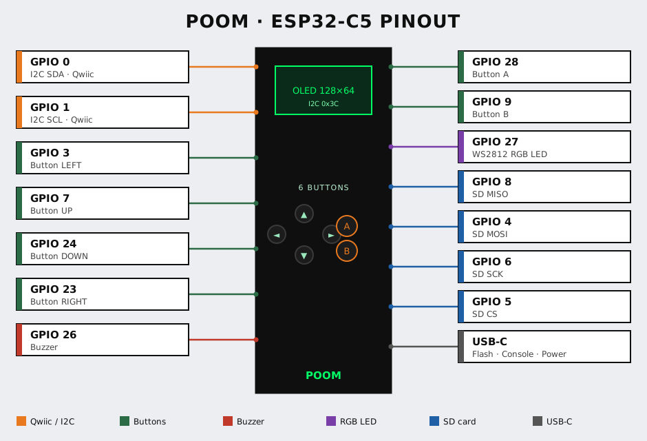
Run it: connect an I2C peripheral to POOM's I2C pins (see Hardware Reference), then THE MAKER → I2C → A.
Observe: each responding device shows up at its 7-bit address (e.g. 0x68 for many IMUs, 0x3C for a common OLED). No address means a wiring or power problem, not a code problem.
Qwiic Deep Dive — Find the Address, Then Use It in Arduino
The Maker mode is built around Qwiic, so this is the full workflow: plug a sensor, discover its I2C address on POOM, then use that address in your own Arduino or Arduboy sketch.
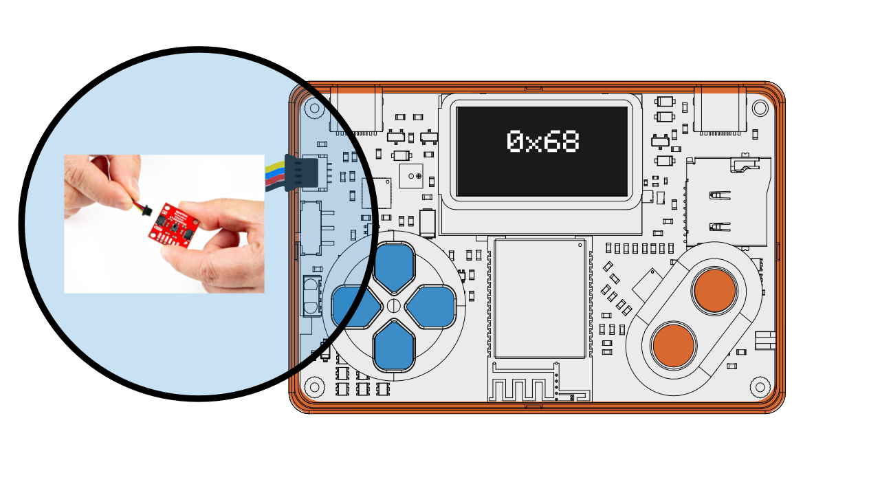
What Qwiic Is
Qwiic is a solderless 4-pin connector (JST-SH) that carries a standard I2C bus: 3.3V, GND, SDA (data) and SCL (clock). The plug is polarized so you can't reverse it, and devices daisy-chain — every sensor shares the same two signal wires and is told apart only by its address. POOM's bus runs at 3.3 V, which matches Qwiic, so you just plug in.
Step 1 — Plug and Scan on POOM
Connect the sensor to POOM's Qwiic port, then run THE MAKER → I2C → A. POOM sweeps the bus and lists the 7-bit address of every device that answers:
I2C scan...
found: 0x68
found: 0x3C
2 device(s)
Here 0x68 is a common IMU (e.g. MPU-6050) and 0x3C a common OLED. Note the address of the sensor you care about — that number is the one thing you need to carry into your code.
Step 2 — Confirm the Address in Arduino
You can reproduce the same scan from the Arduino IDE with the built-in Wire library. This is the classic "I2C scanner" sketch — run it on an Arduino/ESP board wired to the same sensor to double-check the address:
#include <Wire.h>

void setup() {
  Wire.begin();            // SDA/SCL default pins
  Serial.begin(115200);
  Serial.println("I2C scanner");
}

void loop() {
  byte count = 0;
  for (byte addr = 1; addr < 127; addr++) {
    Wire.beginTransmission(addr);
    if (Wire.endTransmission() == 0) {      // 0 = device ACKed
      Serial.print("found 0x");
      Serial.println(addr, HEX);
      count++;
    }
  }
  Serial.print(count); Serial.println(" device(s)");
  delay(2000);
}
Whatever POOM's scanner shows and whatever this sketch prints should match — that's your confirmation the wiring is good and the address is right.
Step 3 — Use the Address in Your Sketch
Once you know the address, you talk to the device by naming it. Minimal example reading the "who am I" register of an IMU found at 0x68:
#include <Wire.h>

const byte DEV = 0x68;     // <-- the address POOM's scanner reported

void setup() {
  Wire.begin();
  Serial.begin(115200);

  Wire.beginTransmission(DEV);
  Wire.write(0x75);              // WHO_AM_I register
  Wire.endTransmission(false);   // repeated start
  Wire.requestFrom(DEV, (byte)1);
  if (Wire.available()) {
    Serial.print("WHO_AM_I = 0x");
    Serial.println(Wire.read(), HEX);
  }
}

void loop() {}
The pattern is always the same: beginTransmission(addr) → write(register) → requestFrom(addr, n) → read(). Swap 0x68 for whatever POOM reported and the register for the one in your sensor's datasheet.
Wire calls work inside an Arduboy sketch running on POOM — use the address POOM's I2C scanner gave you to read a sensor while your game or visual runs on the OLED. That's the bridge between Arduboy games and Maker sensors.Arduino Projects
These are real Maker projects that run on POOM (ESP32-C5) as Arduino sketches. They all build on the POOM Arduboy library for the screen and buttons, and each adds an I2C peripheral over Qwiic — so they double as worked examples of the find-the-address-then-use-it workflow above. Build and flash them the same way as any POOM Arduboy sketch (arduino-cli with --fqbn esp32:esp32:esp32c5).
#include <Arduboy2.h>). Extra parts and libraries are listed per project below.BME688 Air Quality
Turns POOM into a pocket environmental monitor: it reads a Bosch BME688 gas/climate sensor over I2C and shows temperature, humidity, pressure and air-quality (IAQ / CO₂-equivalent) on the OLED. Comes in a few flavours — a minimal register probe, an air aura build using Bosch's BSEC2 IAQ engine, a field-air demo with the FieldAir tuning, and a multi-mode reel menu (air / temp / CO₂ / breath / altitude / weather).
What you need:
- Bosch BME688 (or BME680) breakout, connected via Qwiic/I2C — I2C address
0x77(some boards use0x76). - Arduino libraries: Bosch BME68x and, for the IAQ/BSEC builds, Bosch BSEC2 (both are bundled in the project folders).
- POOM Arduboy library for the display.
0x77. If you see 0x76 instead, change the address in the sketch.NeoKey Projects
Uses an Adafruit NeoKey 1x4 — a four-key mechanical keypad with per-key RGB, all over I2C. Three sketches: a Simon-style memory game, a whack-a-mole reaction game (with tones on C/D/E/G), and a BLE HID controller that maps the four keys to keyboard keys (A / S / J / K) for rhythm games on a computer.
What you need:
- Adafruit NeoKey 1x4 keypad, connected via Qwiic/I2C — I2C address
0x30. - Arduino library: Adafruit NeoKey 1x4 (pulls in Adafruit Seesaw).
- For the online controller only: a BLE HID keyboard library (the project uses
HijelHID_BLEKeyboard). - POOM Arduboy library for the display.
Air Mouse (IMU → BLE)
Reads POOM's motion from an LSM6DS-family IMU and turns tilt/movement into cursor motion, sent to a computer or phone as a Bluetooth mouse. A compact demo of fusing accelerometer/gyro data into pointer control.
What you need:
- An LSM6DS IMU on the I2C bus — address
0x6A(or0x6B). - Arduino library: a BLE mouse library exposing
BleMouse(ESP32 BLE). - POOM Arduboy library for the on-screen status.
.ino, select the ESP32-C5 board, compile (arduino-cli compile --fqbn esp32:esp32:esp32c5 <folder>), then flash the merged .bin with the game flasher or the SD loader — the same flow described in Arduboy Games & Flasher. Remember a project image replaces the POOM multitool; re-flash poom.bin to get it back.Experiment 2 — PLOT: Stream Data Live
What it does: PLOT streams values out for real-time visualization. The BLE plot transport (poom_ble_plot) sends ASCII lines over a BLE notification characteristic, so a companion plotter on your computer can graph them as they arrive. Paired with the IMU stream (poom_imu_stream), you can watch motion data live.
Run it: THE MAKER → PLOT → A, connect from your plotting client, and move the device.
Observe: the line moves with the sensor. This is your feedback loop for tuning thresholds before committing them to firmware.
Experiment 3 — EDGE AI: Capture for Edge Impulse
What it does: the Edge Impulse integration (poom_edge_impulse) connects POOM to Wi-Fi and uploads captured sensor data to an Edge Impulse project, so you can build a gesture/vibration/audio model from real device data. It uses the API token/key you store via the CLI.
Run it:
# In the CLI, store your Wi-Fi and Edge Impulse credentials once:
cfg-wifi-set MyLabAP labpassword
cfg-edge-token-set <your-edge-impulse-token>
cfg-edge-api-key-set <your-edge-impulse-api-key>
Then THE MAKER → EDGE AI → A to connect and upload samples.
Observe: samples appear in your Edge Impulse project's data acquisition view. From there the ML workflow is entirely in Edge Impulse; POOM is the capture front-end.
Experiment 4 — BLE SCAN: Survey the Bluetooth Neighbourhood
What it does: a passive BLE scanner that lists advertising devices with their address and signal. Unlike the offensive TRACKER in THE BEAST, this is a plain maker's survey tool — "what BLE things are around me and how strong are they?"
Run it: THE MAKER → BLE SCAN → A.
Observe: use it to confirm your own sensor or wearable is advertising, and to read its RSSI while you position it.
Where to Go Next
Automate any of this without a rebuild in the Lua Scripting lab. The I2C, SD and sensor wiring is in the Hardware Reference, and the credential commands are covered in the CLI Console.